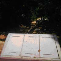
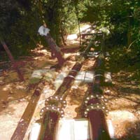
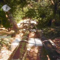
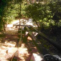
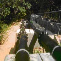
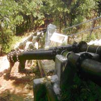
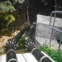
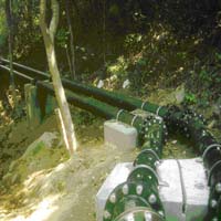
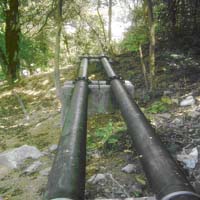
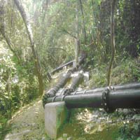
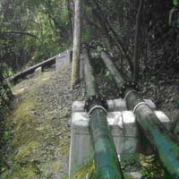
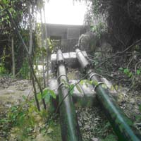
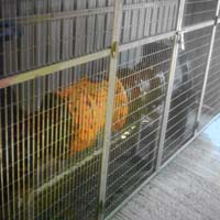
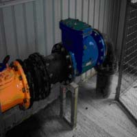
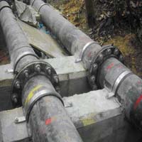
Lists B - The Chinese University of Hong Kong project: Two main ductile iron feed up pipelines of
diameter 200mm for fresh water supply from Tai Po road directed to the main water meter of the University.
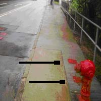
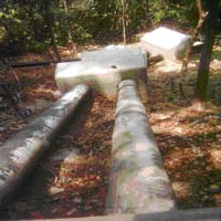
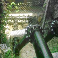
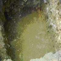
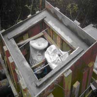
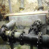
Below pictures show the pipe work arrangement :
|
|
|
|
|
|
|
|
|
|
|
|
|
|
|
|
|
|
|
|
|
|||
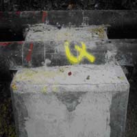
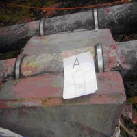
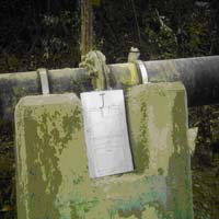
Reference information of the thrust blocks for supporting the pipeline �V
Below data recorded the excavated bulk size of the thrust blocks :
| Thrust blocks I.D. code | Height (mm) | Length (mm) | Width (mm) | Remarks |
| A | 860 | 890 | 1240 | 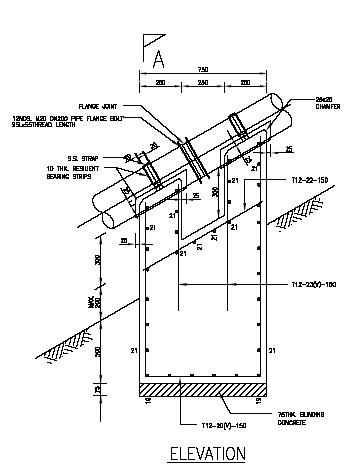
|
| B | 790 | 780 | 1190 | |
| C | 1050 | 780 | 1250 | |
| D | 980 | 790 | 1260 | |
| E | 1000 | 800 | 1260 | |
| F | 930 | 840 | 1160 | |
| G | 960 | 840 | 1200 | |
| H | 820 | 800 | 1200 | |
| I | 800 | 740 | 1200 | |
| J | 1070 | 770 | 1240 | |
| K | 940 | 760 | 1240 | |
| L | 930 | 760 | 1220 | |
| M | 920 | 770 | 1200 | |
| N | 920 | 720 | 1100 | 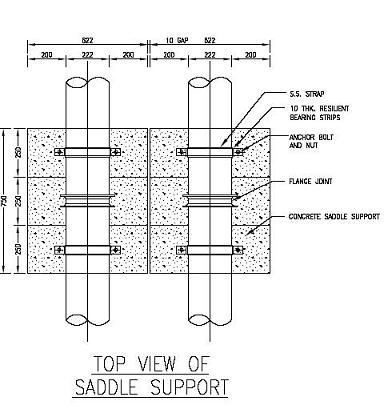
|
| O | 920 | 760 | 1100 | |
| P | 900 | 740 | 1200 | |
| Q | 900 | 740 | 1200 | |
| R | 980 | 780 | 1180 | |
| S | 1100 | 800 | 1220 | |
| T | 1220 | 770 | 1760 | |
| U | 1180 | 1200 | 300 | |
| V | 890 | 380 | 380 | Average size of thrust block approx. 1,032(H) x 814(L) x 1113(W)
|
| W | 890 | 380 | 380 | |
| 5 | 1600 | 1470 | 1070 | |
| 6 (Valve chamber) | 2250 | 1300 | 1070 |
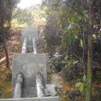
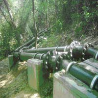
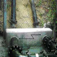
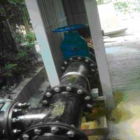
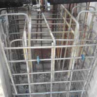
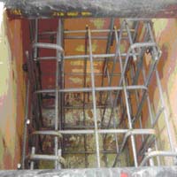
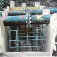
Below pictures show the structure of the thrust blocks :
 |
 |
 |
 |
 |
 |
 |
 |
 |
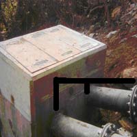 |
Pipe from Tai Po Road, inlets of the valve chamber |
 |
 Back to Our Staff Page