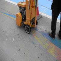
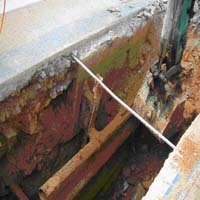
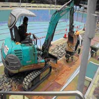
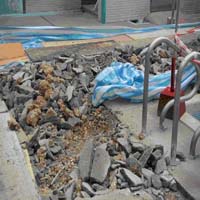
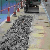
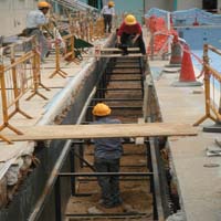
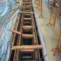
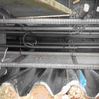
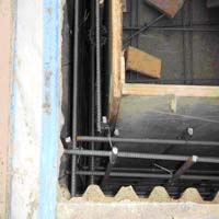
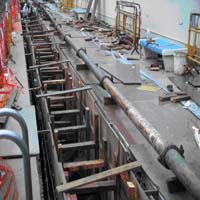
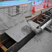
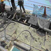
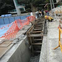
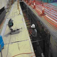
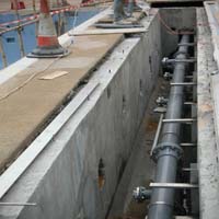
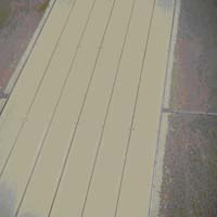
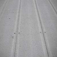
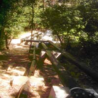
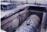
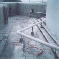
Lists A - Construction of a tunnel for laying down of a ductile iron pipelines. Work located besides
the desk area of the Swimming Pool near the view station. Different work type is involved such as excavation for tunnel direction, formwork for reinforcement concrete, site suit for concrete and metal work for work place protection and structure for pre-cast tunnel cover.
Below pictures show the pipe work arrangement :
|
|
|
|
|
|
|
|
|
|
|
|
|
|
|
|
|
|
||
Appendix B - Reference pictures :
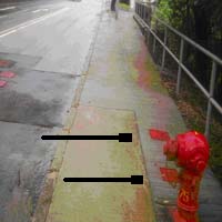
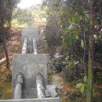
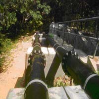
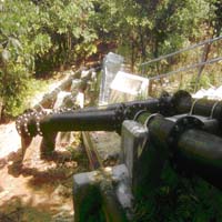
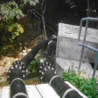
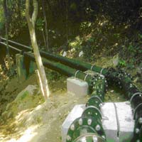
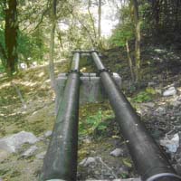
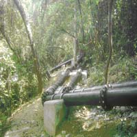
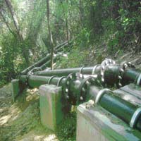
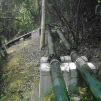
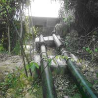
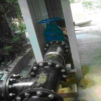
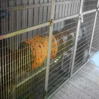
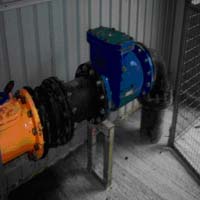
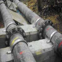
Lists B - The Chinese University of Hong Kong project: Two main ductile iron feed up pipelines of
diameter 200mm for fresh water supply from Tai Po road directed to the main water meter of the University.
Below pictures show the pipe work arrangement :
 |
 |
 |
 |
 |
 |
 |
 |
 |
 |
 |
 |
 |
 |
 |
 |
 |
 |
 |
 |
 |
|||
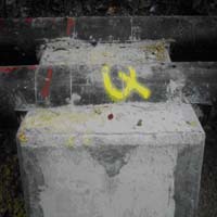
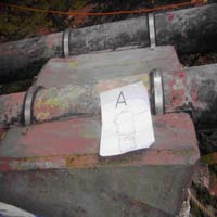
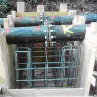
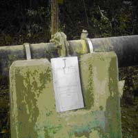
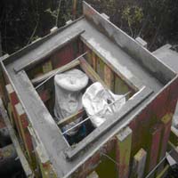
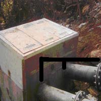
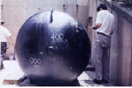
Reference information of the thrust blocks for supporting the pipeline �V
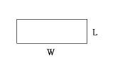
Below data recorded the excavated bulk size of the thrust blocks :
| Thrust blocks I.D. code | Height (mm) | Length (mm) | Width (mm) | Remarks |
| A | 860 | 890 | 1240 | 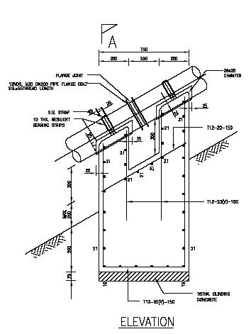
|
| B | 790 | 780 | 1190 | |
| C | 1050 | 780 | 1250 | |
| D | 980 | 790 | 1260 | |
| E | 1000 | 800 | 1260 | |
| F | 930 | 840 | 1160 | |
| G | 960 | 840 | 1200 | |
| H | 820 | 800 | 1200 | |
| I | 800 | 740 | 1200 | |
| J | 1070 | 770 | 1240 | |
| K | 940 | 760 | 1240 | |
| L | 930 | 760 | 1220 | |
| M | 920 | 770 | 1200 | |
| N | 920 | 720 | 1100 | 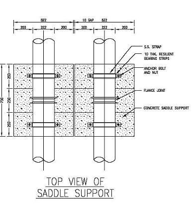
|
| O | 920 | 760 | 1100 | |
| P | 900 | 740 | 1200 | |
| Q | 900 | 740 | 1200 | |
| R | 980 | 780 | 1180 | |
| S | 1100 | 800 | 1220 | |
| T | 1220 | 770 | 1760 | |
| U | 1180 | 1200 | 300 | |
| V | 890 | 380 | 380 | Average size of thrust block approx. 1,032(H) x 814(L) x 1113(W)
|
| W | 890 | 380 | 380 | |
| 5 | 1600 | 1470 | 1070 | |
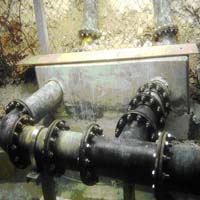
| 6 (Valve chamber) | 2250 | 1300 | 1070 |
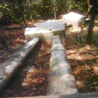
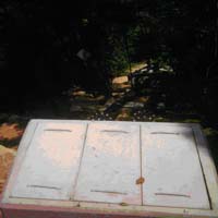
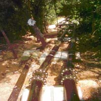
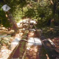
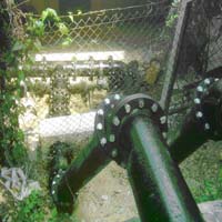
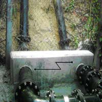
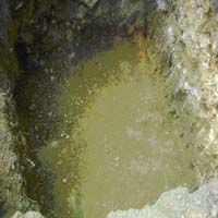
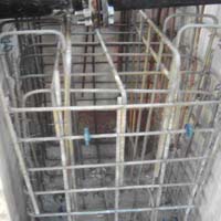
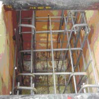
Below pictures show the structure of the thrust blocks :
 |
 |
 |
 |
 |
 |
 |
 |
 |
 |
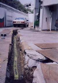
Pipe from Tai Po Road, inlets of the valve chamber |
 |
Appendix C - Reference pictures :
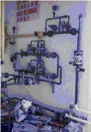
Lists C -Installation and repairing of the gas supply main (different diameters) at Public Estate,
New Territory. Works include the high pressure test for main and operating procedures for LPG Compound for gas supply.
Below pictures show the appearance of the gas equipments at the gas supply station :
 |
 |
 |
 |
 |
|||
 Back to Introducing Page